HIGH VACUUM ENGINEERING
Two-Step High-Vacuum Poppet Valves
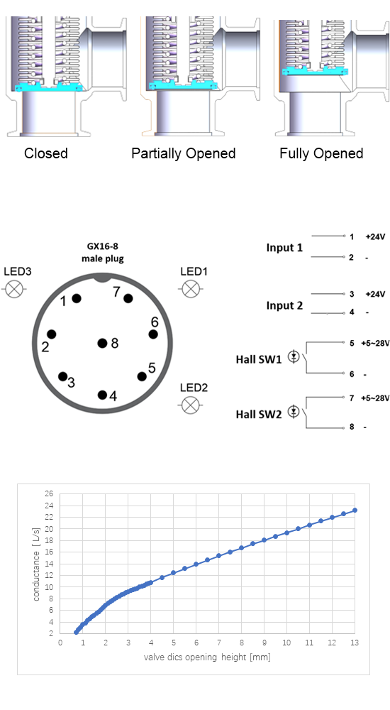
Miro DAC/DLC two-step high-vacuum poppet valves support closed, partially open and fully open states, with an adjustable 0.7–3.7 mm partial opening and control documentation.
Two-step vacuum valve (DAC, DLC)
Note: For external dimensions and 3D models, please refer to the All-in-one vacuum valve.
Control method:
By controlling the voltage signals of Input1 and Input2, the valve can be in three states: closed, fully open, or partially open. The valve is normally closed, i.e., it is in a closed state when powered off.
| Input 1 | Input 2 | Valve states | Signal output | Signal indication |
| 0V | 0V | Closed | SW2 closed | LED2 on |
| 0V or 24V | 24V | Fully open | SW1 closed | LED1 on |
| 24V | 0V | Partially open | LED3 on |
Adjusting the height of the valve plate when partially open:
1. Set the valve to the partially open state: Input 1 receives a 24 V signal, while Input 2 receives no signal.
2. The adjustable poppet-opening range is 0.7–3.7 mm. The factory default is 0.7 mm; a minimum opening of 0.4 mm is available on request.
3. Press and hold the Up button. LED3 flashes every 0.5 s, and the poppet moves upward by 0.04 mm per flash, up to 3.7 mm. When the button is released, the position is saved and retained after power loss.
4. Press and hold the Down button. LED3 flashes every 0.5 s, and the poppet moves downward by 0.04 mm per flash, down to 0.7 mm. When the button is released, the position is saved and retained after power loss.
5. With actuation gas connected: Press and hold the Up/Down button; the poppet moves up/down by 0.04 mm every 0.5 s.
Without actuation gas connected: Press and hold the Up/Down button; the poppet position setting is saved in the valve.
Example: Starting from the factory setting of 0.7 mm, holding the Up button for 15 s produces 30 LED flashes, so the partially open poppet position is 0.7 + 0.04 × (15 / 0.5) = 1.9 mm.
Parameters
| Available port sizes | ISO-K DN63,KF50,KF40 |
| Body material | A6061 aluminum or SUS316L stainless steel (one-piece, weld-free construction; mirror-polished surfaces). |
| Dynamic seal | SUS316L metal corrugated bellows |
| Actuation gas | Clean compressed air or inert gas (filter precision grade ISO8573-15.4.4), 6mm inlet pipe |
| Actuation pressure | 3.0±0.2 bar |
| External Leakage* | <1 × 10⁻¹¹ Pa·m³/s (1 × 10⁻¹⁰ mbar·L/s) |
| Internal Leakage* | <1 × 10⁻¹⁰ Pa·m³/s (1 × 10⁻⁹ mbar·L/s) |
| Operating pressure | 1×10⁻⁹ mbar to 2000 mbar |
| Maximum forward operating pressure | 2000mbar |
| Maximum reverse operating pressure | 1200mbar |
| Sealing material | FKM |
| Maximum process-gas temperature | < 250 °C (with the valve body maintained at room temperature) |
| Solenoid voltage | 24 V (±5%) |
| Magnetic switch parameters | Operating voltage: 5–28 V; leakage current: 6 μA; voltage drop: approximately 2.5 V; maximum operating current: 0.5 A (0.35 A with short-circuit protection). |
*Note 1: The external leakage rate is defined as the rate at which external air permeates into the interior of the valve, mainly influenced by the quality of the sealing surface and the material of the O-rings. External leakage can be detected through external helium testing (poor quality sealing surfaces may rely on vacuum grease for temporary sealing, but vacuum grease will fail over time, leading to increased external leakage. Additionally, vacuum grease can also increase the internal leakage).
*Note 2: The internal leakage rate is influenced by the cleanliness inside the valve and the degassing performance of the internal materials. Oil and water stains can significantly increase the internal leakage rate (manifested as extremely high background levels in leak detectors). Dust, O-ring materials, and the internal surface quality of metal materials are also influencing factors, such as porous anodic oxide layers that can severely affect the internal leakage rate.